Blog Post 12: Preliminary FEA for Design Concept 3
- Sam Jones
- Apr 13, 2020
- 4 min read
Updated: Aug 9, 2020
Here are the results from the first round of Finite Element Analysis I carried out on my third design concept:
Body Gripper:
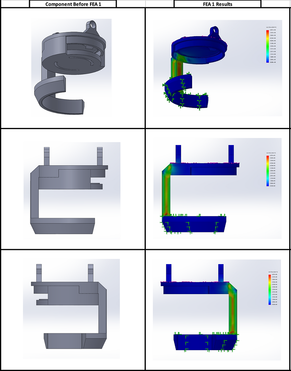


I simulated working forces on Concept 3’s main gripper by fixing the bottom geometry (this ideally will remain static when it grips the jar) and applying torque to the top where the rotating middle section is to be housed. The torque value used in this study was 5Nm acting anti-clockwise, this served to simulate the opposing torque that would be endured by the rest of the device before the lid gives way. The results shown above indicate that the arm connecting the jar gripper to the housing cannot in its current state tolerate this amount of reactive torsional force. Therefore, moving into the next iteration of this component, addition of support material on either side of this area is the obvious next step in producing a structurally sound component.
Middle Section:


With the two vertical lid grippers being fixed as they should be according to the device’s intended operation, I applied 5Nm of clockwise torque to the middle section as shown above. The results indicate that one of these grippers will be susceptible to failure at its base and so reinforcing the area as well as removing obsolete material from the middle of the component progressing through the design process should be a top priority.
Spring Force Calculations:
Here are the calculations I made to find the spring force needed to clamp the gripper onto the lid so that it will not slip when the 5Nm of torque required to loosen them is applied:

Gripper:


You can see how the gripper in its current state faired when I subjected it to simulated compression spring force as well as reactive force normal to the jar lid. The normal force I used for this simulation was 190.56N – double the value calculated for the Concept 1 preliminary FEA due to there being just 1 gripper in this case, the force for each spring was 95.28N. Along with this, 5Nm of anticlockwise torque was applied to the gripping surface. Running this FEA has yielded results showing two points of failure on either side of the spring mount structure. You can see that it also highlighted a substantial material surplus above the gripping surface. The addition of support material at the edges of the spring mounts would be the best course of action at this stage to ensure that the component will be able to withstand the high forces exerted by both the compression springs and the jar lid simultaneously.
Calculating Handle v1 Force:
In an effort to collect the most accurate FEA results possible for the handle, I have taken the time to calculate the minimum downward force on the handle required to loosen the jar lid.

Seeing as the only known force variable in the operation of the device is the torque required to open standard jar lids, the forces acting on the gripping surface, bevel gear 1 and bevel gear 2 respectively must be deduced. The diagram above shows how the two bevel gears are positioned, with the first gear attached to the middle section serving to bring about rotation in the component (and in turn the gripper) parallel to the base, and the second gear attached to the handle converting linear force to rotational force perpendicular to the base.

The simplified force diagram above shows how I have taken the moments at bevel gear 1 and the gripper, and used these to calculate the unknown variable that is Fg1. Given the intended anti-clockwise motion of the middle section/gripper, Fg1 must be greater than FL. Using this logic, and knowing both the distance from the pivot to the gripping surface and the approximate distance from the pivot to the gear’s contact point, the unknown force could be calculated (227.27N).

Once the required force for bevel gear 1 had been calculated, the handle and bevel gear 2 could be represented as the simple force/beam diagram shown above. The required force calculated for bevel gear 1 is essentially the force acting in the opposite direction on bevel gear 2, for this reason the method I used to attain that value could be applied to finding the minimum downward force needed to loosen the jar lid (87.17N).
Handle v1:


I attained the results shown above by applying the 87.17N of downward force to the end of the handle, with the gear dowel connections being fixed as these will be static until sufficient inertial force is produced to loosen the jar lid. You can see that two points of failure where the arms join the dowel connections were revealed in this testing and considering the right angles found at those points, it comes as no surprise that these areas are where most of the stress is concentrated. Aside from the back of the model, there is very little stress along the length of the arms, highlighting the presence of non-essential material that could be removed at no cost to the component’s strength.
To do:
Add support material to the sides of the static body gripper as FEA results indicate that this area will be prone to failure when the device is subject to the opposing torsional force created by the middle section (lid gripper) rotating a jar lid.
Add support material to the base of the traction pads located on the underside of the middle section as well as the sides of the lid gripper as these areas will experience a torsional force similar to that which must be endured by the body gripper.
Remove obsolete material from all components.


Comments